Production Flow
This page reviews the production flow for both data and simulations. Even if the reconstruction chain is the same for both samples, there are some discrepancies that need to be taken into account. Additionally, a different chain will be follow depending on the type of simulation, and detector geometry. The cities mentioned along this list are summarised in IC. It is also important to remark that during data acquisition, three different trigger configurations are considered:
Trigger 1: to select low energy events, i.e. Kr events.
Trigger 2: to select high energy events, e.g. Tl events, bb events, etc.
Trigger 0: used for special runs, with specific configurations, such sensor calibration data.
Simulations will be separated depending on which type of generator is used, as Trigger 1 or 2 like events.
Warning
Software is in a constant evolution process, this is a current picture, but it might change in few months. Stay tuned!
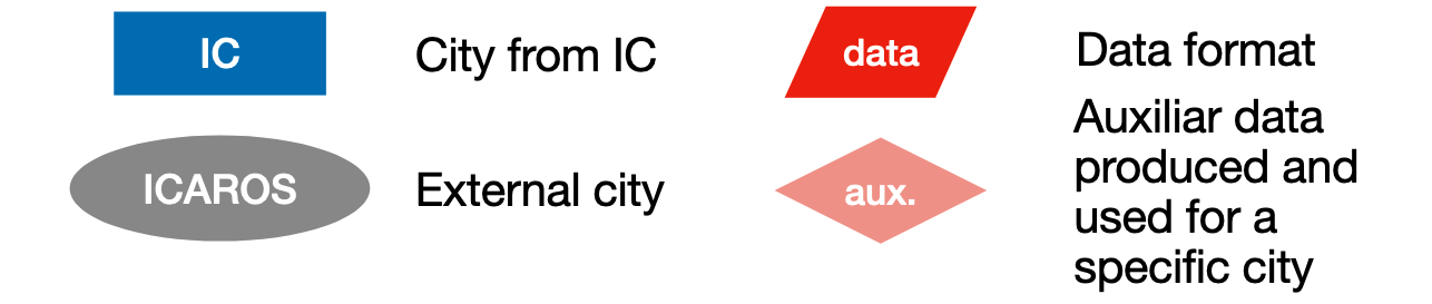
For both samples, when representing the production flow, the type of same legend is used:
Data
Data collected in NEXT detectors is in form of Raw Waveforms (RWF, in ADCs). The following production flow is used over the RWFs for both type of Triggers:
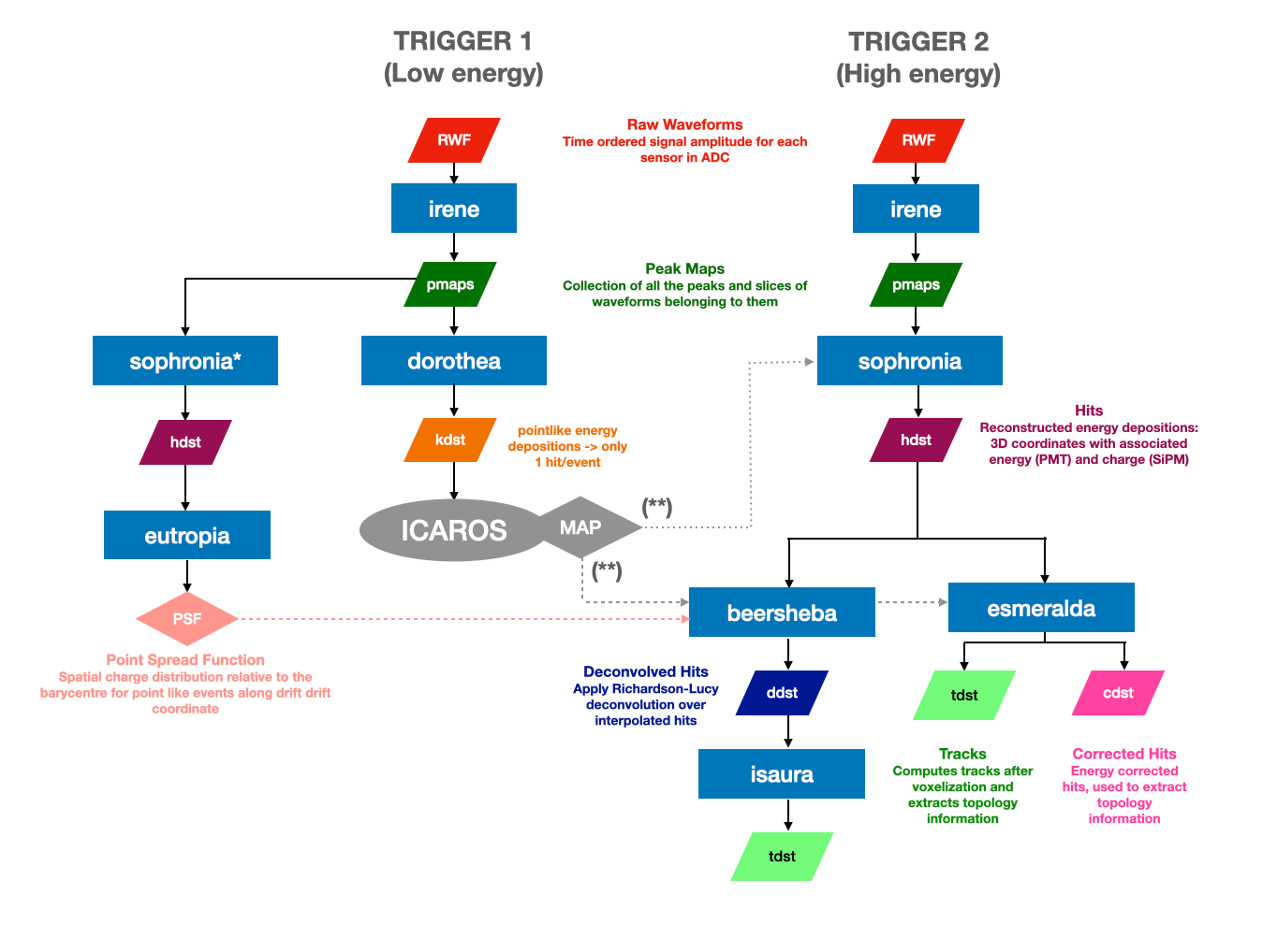
Sensor parameters for Irene need to be updated before any reconstruction. These are obtained from calibration using Phyllis, Trude, and Berenice IC cities. These parameters are updated regularly during detector operation, and are stored in a database. Updates to the database are pushed to the repository, so keeping up to date with the main branch is very much recommended.
Correction maps are obtained from Krypton events (Trigger 1) using ICAROS. Official production correction maps can be found in Official Production. A complete review about how this maps are produced can be found in “How to produce Kr Maps”.
(*) Krypton events (Trigger 1) are used under a specific configuration of Sophronia and Eutropia. Official production PSFs for deconvolution can be found in Official Production.
PSFs are nedeed to run Richardson Lucy deconvolution (Beersheba). A review about how this PSFs are produced can be found in “How to create PSFs for deconvolution (Beersheba)”.
(**) Sophronia and Esmeralda / Beersheba receive different correction maps. During production, Sophronia uses a preliminary correction map from the previous day to generate corrected hits, aiding in real-time data monitoring to catch potential issues early on. Meanwhile, Esmeralda and Beersheba apply the final corrections using a map created from the data of the ongoing Run. As this Run’s processing concludes by the end of the day, the corresponding correction maps are only accessible the following day. For the MC process, only one correction is needed, and there is no distinction between applying it in Sophronia or in the Esmeralda / Beersheba phase.
Note
dst stands for data summary tape
Data Format
Data files are produced under the following name:
run_$RUNNUMBER_$FILENUMBER_ldc$LDCNUMBER_trg$TRIGGER.$CITY.h5
- where each paramter corresponds to:
$RUNNUMBER: number of 5 digits assigned to the run when data is taken.$FILENUMBER: each run is divided in different files starting from 0 and up to 4 digits (0000,9999).$LDCNUMBER: ldc number assigned to the file, it goes from1to7.$TRIGGER: trigger number, it could be0(sensor calibration),1(low-energy Kr),2(high energy events).$CITY: corresponds to the name of the city that has produces the file (eg. pmaps would be namedirene, tracks asisaura). Files produced from the decoder (RWF) will be assinged aswaveforms.
For example, a file created from the decoder would look like this:
run_13017_0001_ldc1_trg0.waveforms.h5
and the corresponding processed files would look like this:
run_13017_0001_ldc1_trg0.irene.h5
run_13017_0001_ldc1_trg0.sophronia.h5
run_13017_0001_ldc1_trg0.esmeralda.h5
Simulations
Simulations do not produce directly RWF, for that reason is required to run additional cities in the production flow. The first type of data format that is constructed from NEXUS files is True Waveforms (TWF, in photoelectrons). To construct them is necessary to take into account which type of simulation is used. NEXUS simulations can be produced including sensors information, like time and detected charge of the sensors (full simulation) or just with the information from the true hits of deposit energy (fast simulations). Depending of this output, a different reconstruction chain will need to be implemented: Buffy or Detsim.
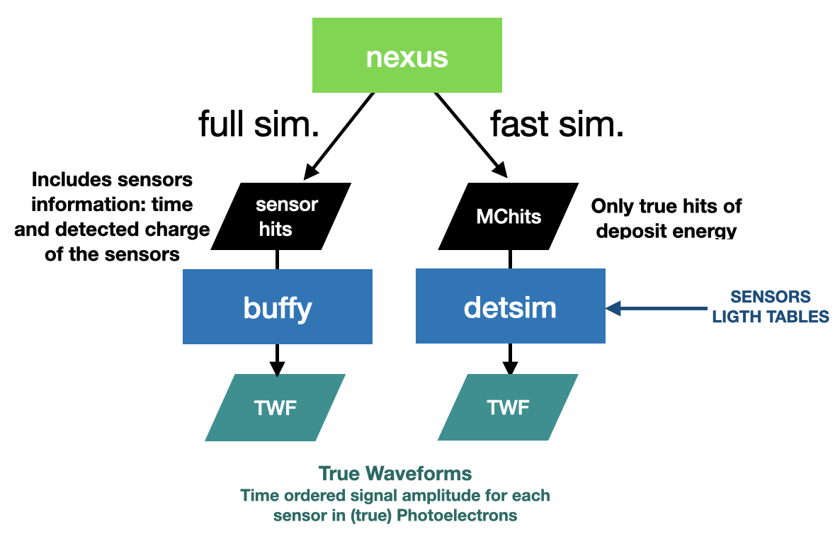
Detsim files require of Lighttables and PSFs. The ones created for official production can be found in Official Production. Otherwise, a review about how they can be created can be found in “How to create Light Tables and PSFs for detsim”.
Once TWFs are created, the simulation production flow take a different way depending on which type of detector is simulated. This is caused by the fact that some of the geometries do not have electronic parameters included in their database. It currently happens for NEXT-100 and NEXT-FLEX geometries. In that case, we produce pmaps directly using Hypathia (pseudo-RWF are created on the fly but not stored). These pseudo-rwf contain only gaussian electronic noise and gain fluctuations in the PMTs while SiPMs have the same processing. For detectors with the electronic parameters included (like DEMOPP or NEXT-White), we can transform TWF into RWF using Diomira.

From this point on, the same production flow than data is used in simulations (see image from Data section).
Note
For simulations, there is not distinction between Trigger 1 or 2 to transform NEXUS files into pmaps.